Rudysmodelrailway implements a railway crossing with blinking lights by introducing a state rdudiagram, which he then in turn implements by switch statements. Here is my take on the state diagram of a (one way) railway crossing with sensor S1 detecting an incoming train and sensor S2 detecting if the train has passed the crossing:
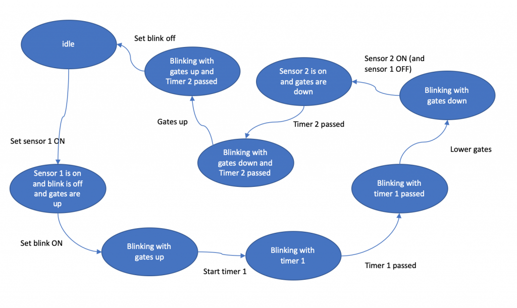
This looks a bit too messy (but maybe I thought a bit too complicated), so let’s split the problem in two parts: In the first part we just have the blinking lights in the second, we add the gates.
Now let’s have a look at the blinking-only version: Let’s assume the sensors are less then one train lengths apart and installed on both sides of the railway crossing. The following pictures give us an impression on what to show when.
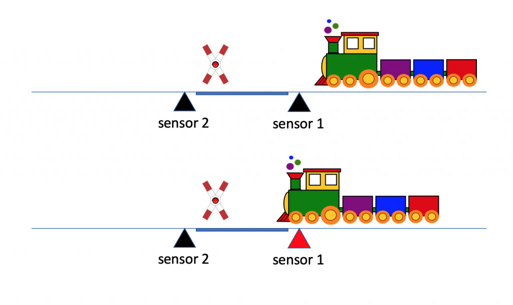
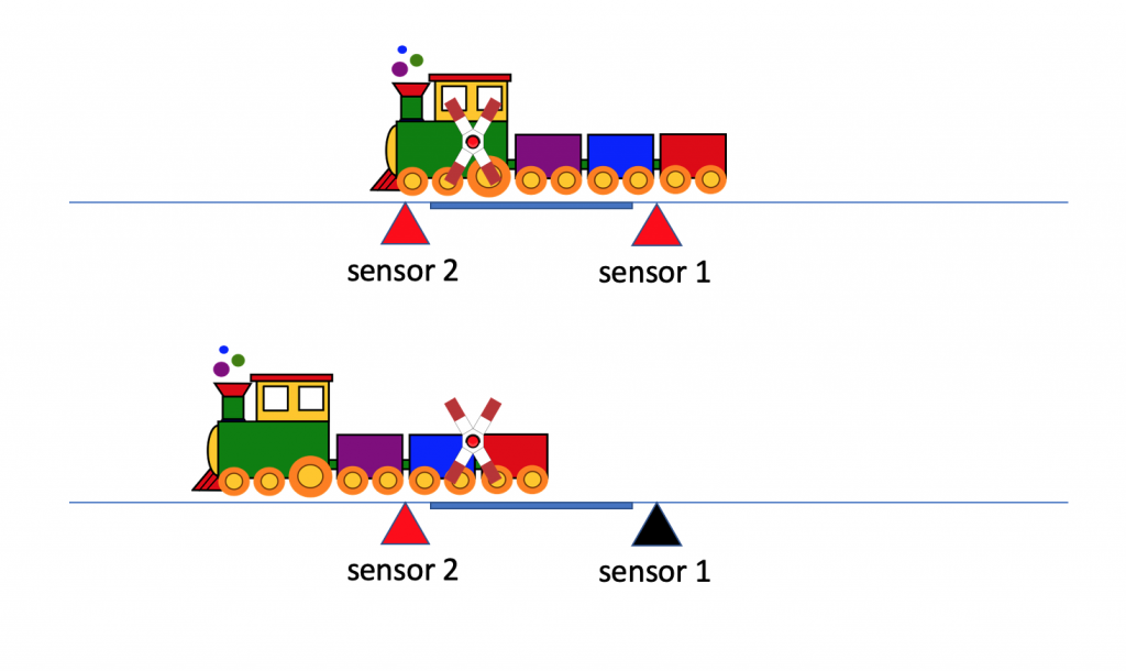
So, the bottom line is: „Blink if at least one sensor is detecting something, otherwise be quiet“. To describe this behavior we use a thing called a ’state transition table‘ (https://en.wikipedia.org/wiki/Finite-state_machine) :[table id=8 /]
This state transition table can be realized as so:
// teensy 3.6

 const unsigned int S1_PORT = 1;
 const unsigned int S2_PORT = 2;
 const unsigned int LED1_PORT = 3;
 const unsigned int LED2_PORT = 4;
 unsigned int blinkingLightsDuration = 300;
 unsigned int blinkingLightsLeft;
 unsigned int blinkingLightsRight;
 unsigned long oldSensorTimer;

 void setup() {
   oldSensorTimer = millis();
   pinMode(LED1_PORT, OUTPUT);
   pinMode(LED2_PORT, OUTPUT);
   pinMode(S1_PORT, INPUT_PULLUP);
   pinMode(S2_PORT, INPUT_PULLUP);
 }

 void loop() {
   unsigned int sensorValue = detectSensor();
   switch (sensorValue) {
     case HIGH:
       blinkingLightsOn();
       break;
     case LOW:
       blinkingLightsOff();
       break;
   }
   blinkingLightsSend();
   delay(123);
 }

 unsigned int detectSensor(void) {
   // if one or both of the buttons are pressed, return 1
   return
    (!digitalRead(S1_PORT) || !digitalRead(S2_PORT)) ? 1 : 0;
 }
 void blinkingLightsOn() {
   unsigned long timer = millis();
   if (timer - oldSensorTimer > blinkingLightsDuration) {
     blinkingLightsLeft =
          (blinkingLightsLeft == LOW) ? HIGH : LOW;
     blinkingLightsRight = !blinkingLightsLeft;
     oldSensorTimer = timer;
   }
 }
 void blinkingLightsOff() {
   blinkingLightsLeft = LOW;
   blinkingLightsRight = LOW;
 }
 void blinkingLightsSend() {
   digitalWrite(LED1_PORT, blinkingLightsLeft);
   digitalWrite(LED2_PORT, blinkingLightsRight);
 }
The loop function looks already a bit messy, but bear in mind we haven’t even introduced the gates yet.
This is one of the standard ways to implement finite state automatons: write down the state transition table and implement it as cascading switch clauses.[table id=9 /]
Here we have a slightly improved version of the state transition table. Instead of text we use a function style syntax. How would this better implemented in C?
To answer this we need a bit of knowledge about function pointers, so have a look at this: http://www.newty.de/fpt/index.html
If you want to understand function pointers a bit better, have a look at http://johnsantic.com/comp/state.html. The way he implements the FSA is quite straight forward, but not at all easy to understand.
Let’s try to implement the transition table in a way similar to John’s way.
// teensy 3.6

// cf. http://johnsantic.com/comp/state.html

 const unsigned int S1_PORT = 1;
 const unsigned int S2_PORT = 2;

 const unsigned int LED1_PORT = 3;
 const unsigned int LED2_PORT = 4;

 unsigned int blinkingLightsDuration = 300;
 unsigned int blinkingLightsLeft;
 unsigned int blinkingLightsRight;
 unsigned long oldSensorTimer;

 void blinkingLightsOn();
 void blinkingLightsOff();
 void doNothing();

 enum States {IS_OFF, IS_ON, MAX_STATES} states;
 enum Events
    {BUTTON_NOT_PRESSED,
       AT_LEAST_ONE_BUTTON_PRESSED, MAX_EVENTS} events;

 // { action_s1_e1, action_s1_e2, action_s1_e3, action_s1_e4 },
 // { action_s2_e1, action_s2_e2, action_s2_e3, action_s2_e4 }

 void (*const state_table [MAX_STATES][MAX_EVENTS]) (void) = {
   { doNothing, blinkingLightsOn },
   { blinkingLightsOff, blinkingLightsOn }
 };

 States state = IS_OFF;

 void setup() {
   oldSensorTimer = millis();
   pinMode(LED1_PORT, OUTPUT);
   pinMode(LED2_PORT, OUTPUT);
   pinMode(S1_PORT, INPUT_PULLUP);
   pinMode(S2_PORT, INPUT_PULLUP);
 }

 void loop() {
   Events event = detectSensor();
   state_table[state][event]();
   delay(123);
 }

 Events detectSensor(void) {
   Events e;
   if (
     LOW == digitalRead(S1_PORT) ||
     LOW == digitalRead(S2_PORT)
   )
     e = AT_LEAST_ONE_BUTTON_PRESSED;
   else
     e = BUTTON_NOT_PRESSED;
   return e;
 }

 void doNothing() {};

 void blinkingLightsOn() {
   unsigned long timer = millis();
   if (timer - oldSensorTimer > blinkingLightsDuration) {
     blinkingLightsLeft =
        (blinkingLightsLeft == LOW) ? HIGH : LOW;
     blinkingLightsRight = !blinkingLightsLeft;
     oldSensorTimer = timer;
   }
   blinkingLightsSend();
   state = IS_ON;
 }

 void blinkingLightsOff() {
   blinkingLightsLeft = LOW;
   blinkingLightsRight = LOW;
   blinkingLightsSend();
   state = IS_OFF;
 }

 void blinkingLightsSend() {
   digitalWrite(LED1_PORT, blinkingLightsLeft);
   digitalWrite(LED2_PORT, blinkingLightsRight);
 }
You find the tricky bits in the loop() function.
It is tricky, because the switch statement has magically disappeared. Instead of the switch statement, you just call (!) an array element, which turns out to be a function, indexed by state and event.
To implement it you have to do this:
- You define an enum for the states of the finite state machine, for your convenience add a MAX_STATES to it. This field is helpful in loops.
- You define an enum for the events of the finite state machine, for your convenience add a MAX_EVENTS to it.
- You define all functions before referring to them.
- You create a two dimensional table with MAX_STATES rows and MAX_EVENTS columns containing pointers to the functions which process the given combination. In case of doNothing() at an empty function…
Example: When the FSM is in state „IS_OFF“ and receives an event „AT_LEAST_ONE_BUTTON_PRESSED“ then the function pointer table is referring to the function blinkingLightsOn(). Thus this function will be called. Within this function the state will be set accordingly (new state: „IS_ON“, leading to a new route, when the next events is read.
How to extend to the final version with railway gates and IR sensors
How IR sensors can replace the simple micro buttons can be learned here:https://cms.vp-consulting.de/arduino-ir-sensor-to-trigger-onboard-led/
If you now want to extend this solution then to the version with gates, it seems to be very easy:
- Add the servo to the sketch.
- Add two function, one for raising the bars, one for lowering them.
- Add these two functions to the functions which now trigger the blinkingLightsSend() function.
If you see the risk the bars are not lowered before the train passes the crossing, place the detectors further apart and add a detector in the middle.
The logic with three sensors seems to be 100% identical.